![]()
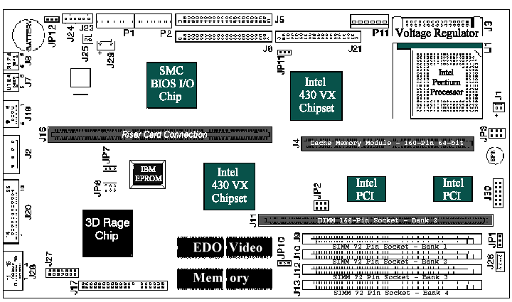
Locations and Descriptions
Note: Usually anything labeled with J(number) is just a location reference. JP(number) are your jumpers.
|
Location |
Description |
NOTES |
|
J3 |
System board voltage regulator |
Can use eighther the shorting Block for standard petium chips or the Voltage Regulator Block for the MMX enabled Pentiums. |
|
J4 |
Cache connector |
No jumpers need to be set. System BIOS will detect the amount of cache. Check system BIOS settings after adding or removing memory to make certain it was recognized. |
|
J5 |
Primary Hard Disk IDE (Hard Disk 1, Hard Disk 2) |
According to IBM a second hard drive must be installed on the secondary Hard Disk IDE connector. |
|
J6 |
Secondary Hard Disk IDE (Hard Disk 3 or CD-ROM, Hard Disk 4) |
See note above. |
|
J9 |
SIMM 72-pin Socket - Bank 1 |
No jumpers need to be set. System BIOS will detect the amount of cache. Check system BIOS settings after adding or removing memory to make certain it was recognized. |
|
J10 |
SIMM 72-pin Socket - Bank 2 |
No jumpers need to be set. System BIOS will detect the amount of cache. Check system BIOS settings after adding or removing memory to make certain it was recognized. |
|
J12 |
SIMM 72-pin Socket - Bank 3 |
No jumpers need to be set. System BIOS will detect the amount of cache. Check system BIOS settings after adding or removing memory to make certain it was recognized. |
|
J13 |
SIMM 72-pin Socket - Bank 4 |
No jumpers need to be set. System BIOS will detect the amount of cache. Check system BIOS settings after adding or removing memory to make certain it was recognized. |
|
J11 |
DIMM 168-pin Socket - Bank 2 |
No jumpers need to be set. System BIOS will detect the amount of cache. Check system BIOS settings after adding or removing memory to make certain it was recognized. |
Jumpers and Settings
|
Jumper |
Settings |
NOTES |
|
JP2 |
System board bus clock |
|
|
JP3 |
Processor Frequency Ratio |
|
|
JP10 |
VGA Jumper If using onboard Video then set 1-2, If you want to replace with another card then disable by setting jumpers 2-3 |
The ATI 3D Rage chip and Video Memory are soldered to the motherboard. They cannot be removed. |
|
JP12 |
Power-on Password Reset (Normally set to 1-2 To clear BIOS settings from memory move to 2-3 then reset back to original 1-2. |
Usually flashing the BIOS is all you would need to do. |
|
JP11 |
Diskette Drive write enable 1-2, or disable by removing jumper. |
A Hard Drive jumper would be more usefull. |
![]()